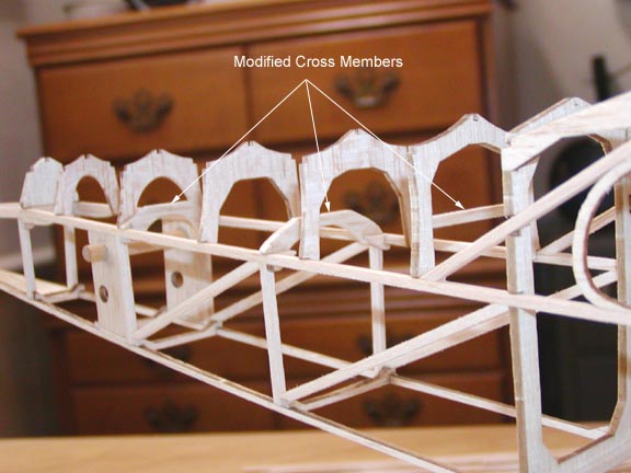
This view looking forward shows how far off center the PVC burst tube is relative to the rubber motor peg. Question: If this is going to cause a problem when winding the rubber motor, then I should once again cut out the two arched cross members that are holding the burst tube down and provide new cross members that will allow the burst tube to center on the rubber motor peg. However, back this far, it may not matter. Please advise at your earliest opportunity..................Tandy
The picture below shows the 3/4" PVC burst tube inserted through the hole in the front bulkhead and running all of the way back to the rubber motor pin (Duke Horn told me it is peg, which I shall call it from now on). As you can see, the arched cross members keep the PVC burst tube from centering on the rubber motor peg in the back, which will be shown more clearly in the next picture. Question (2): How far should the PVC burst tube extend out in front of the fuselage's front bulkhead?

Notice in the picture above, left, that a 3/16" O.D. aluminum tube has replaced the 3/16" wooden dowel for the rubber motor peg. Duke Horn recommended this in order to be able to wind the rubber motor on a stooge. He suggested I flare one side of the aluminum tube and drill a small hole in the other side for a wire to retain the motor peg, which I will do...
I got a great recommendation from Jim O'Reilly this afternoon for the blast tube. It called a blast tube or burst tube? Anyway, Jim said: "I'd recommend that the blast tube have a slot in its back end that is a push-fit over the rear motor anchor. If you want to get really fancy, you can make it a 90 deg. Angle slot so that you can push it onto the rear motor anchor and then twist it a bit to hold it there when you pull the motor out to stretch it before you start winding." Of course, this meant that the three modified cross members shown below had to be cut out so the blast tube would center on the motor peg, which I did.
Tandy I would take out the arches and instead install horizontal 1/16 x 1/4 balsa strips against all top formers aft of the cabin. Install approx 1/2 way up on ea one ahead of the rear tube. Overlap these so that they are o/side to o/side. These will add a lot to the compression strength of the rear fuse and give plenty of motor clearance( tube ) Mike
In the message above, Mike Midkiff provided me with an excellent recommendation on a sudo cross member structure for the top longerons in the aft part of the fuselage. The picture below shows the 4 added cross members as per Mike's suggestion. Thanks Mike!

For additional support, I added the 4 small gussets to tie in the bottom of the two bulkheads on either side of the fuselage side's vertical truss member to the top longeron. This adds very little weight, but a lot of support.


I'll swear, building and modifying the construction of this rubber model is becoming a big challenge, more so than I would have ever thought possible. I spent more than two hours this afternoon just cutting and shaping the cut outs in the end of the PVC blast tube to receive the 3/16" aluminum motor peg. The PVC is somewhat difficult to work with. However, as the picture below shows, I finally accomplished the task that Jim has recommended.

With the three modified cross members removed from the fuselage structure, the blast tube can now be inserted into the fuselage, slipped over the motor peg, and locked into place with a quarter twist as shown below. As you can see, the 3/4" blast tube just barely fits inside the fuselage sides back at the motor peg.

As the picture below shows, the cross members were kept as low as possible on the bulkhead legs, but still provided upper clearance for the blast tube. Notice the thin section of fuel tubing keeping the 3/16" aluminum motor peg in place (an input from Gene Wallock).

The stabilizer and elevator spline paper patterns were traced from the plan and cut them out. Then the two stabilizer and elevator spline templates were made out of 3/32" card board. If you remember, Mike Midkiff recommended that the stabilizer and elevator be made a single unit structure. So after waxing the edges of the templates entire perimeter, they were pinned down on the plan. Three pieces of the scrap 3/32" card board were glued to the two templates as shown below to lock them together. Three long 1/24" X 1/8" strips were stripped off from 1/8" sheet balsa and are currently soaking in hot water. These strips are long enough to form the spline completely around the left side of the horizontal tail. The composite template below has to be used again to make the right side of the stab spline. ....................Tandy